
What is turbo lag?
Understand what turbo lag is, how it differs from boost threshold, and how to diagnose sluggish throttle response. Expert mechanical advice by autoKUR.
What is turbo lag: definition and underlying mechanics
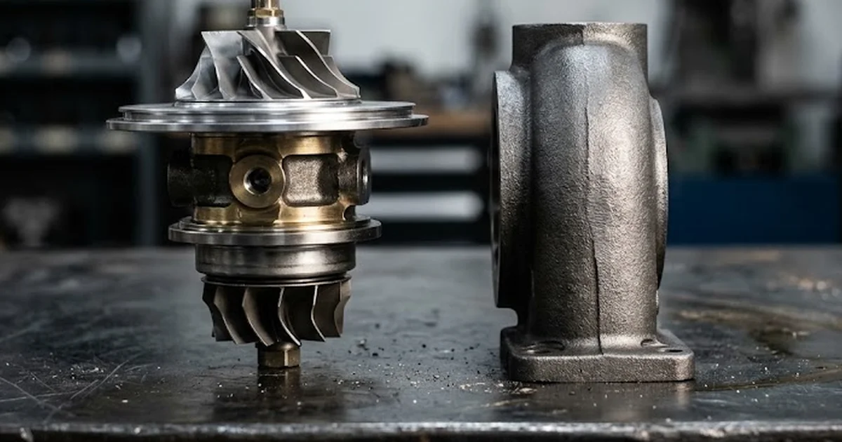
Turbo lag refers to the brief hesitation between the moment you depress the accelerator pedal and the moment the turbocharger delivers noticeable boost pressure and acceleration. For both everyday drivers and experienced workshop technicians, understanding this phenomenon requires looking at the physical working principles of forced induction. Unlike a supercharger, which is mechanically connected to the engine crankshaft via a belt or gear drive, a turbocharger relies entirely on the kinetic and thermal energy of expanding exhaust gases. To understand the wider system context, reviewing how a turbocharger works provides essential foundation for seeing why this delay occurs naturally during transient operating phases.
When an engine is idling or cruising under light load, the volume and temperature of exhaust gases flowing through the exhaust manifold remain modest. Depressing the throttle demands instant power, but the compressor wheel cannot compress intake air until the turbine wheel has accelerated to operational velocity. As documented in an authoritative University of Cambridge study on transient response, rated torque and power for downsized units are recovered by means of turbocharging, but the transient response of such engines is affected by the static and dynamic characteristics of the turbo-machinery. In passenger vehicles, this transient response delay typically ranges between 0.5 to 1.5 seconds in conventional turbocharged engines before optimal boost levels are attained.
The sequence that converts a driver throttle request into positive intake manifold pressure involves several physical stages:
- Throttle opening and fueling adjustment: The throttle plate opens or direct injection volume increases, admitting extra air and fuel into the combustion chambers.
- Combustion pressure wave generation: The ignited fuel mixture burns, producing a higher volume of hot exhaust gas that rushes past the exhaust valves into the manifold.
- Turbine wheel acceleration: The high-velocity exhaust flow enters the turbine housing, striking the turbine blades and overcoming the static and rotational inertia of the assembly.
- Shaft power transfer: The rigid central shaft transfers rotational torque to the compressor wheel housed on the intake side.
- Compressor wheel pressurization: The compressor inducer draws in ambient air, accelerating it radially through the diffuser and compressor scroll, which converts velocity into static boost pressure.
- Plenum charge equalization: Pressurized air travels through the charge pipes and intercooler core, finally filling the intake manifold to deliver enhanced engine torque.
Turbo lag vs boost threshold: understanding the key difference
In technical discussions, drivers and mechanics frequently conflate turbo lag with boost threshold. Although both manifest as a lack of immediate low-end power, their underlying causes, engine operating conditions, and engineering solutions differ fundamentally. Distinguishing between them is crucial when evaluating vehicle performance or diagnosing engine hesitation in a workshop.
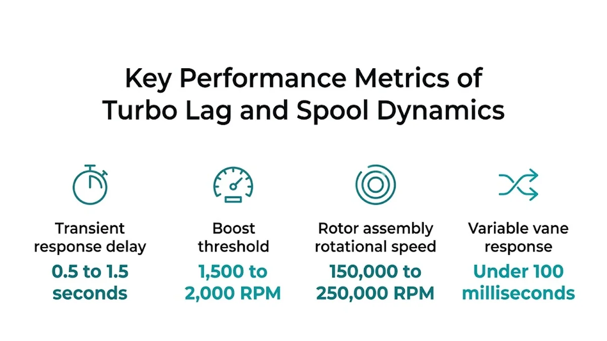
Boost threshold defines the minimum engine speed (RPM) at which the engine produces sufficient exhaust gas volume and heat energy to spin the turbine fast enough to generate positive manifold pressure under full load. Below this engine speed, the turbocharger simply cannot produce boost regardless of throttle duration. In most modern passenger cars, the boost threshold is often situated between 1,500 to 2,000 RPM depending on displacement and manifold geometry. If you open the throttle at 1,100 RPM in fourth gear and wait three seconds for acceleration to pick up as the engine climbs past 1,800 RPM, you are experiencing the vehicle operating below its boost threshold, not classic turbo lag.
In contrast, turbo lag is an exclusively transient delay. It occurs when the engine is already operating well above its boost threshold RPM—for instance, cruising at 2,800 RPM off-throttle—and the driver suddenly requests full acceleration. Even though the engine speed is optimal, the exhaust flow was minimal while coasting. The fraction of a second required for the rotating components to accelerate from an idle coasting speed to their working operational speed represents true turbo lag.
| Parameter | Turbo Lag | Boost Threshold |
|---|---|---|
| Definition | Time delay to reach target boost after throttle application while operating within the boostable RPM range. | Minimum engine speed (RPM) required to generate positive manifold boost pressure under sustained wide-open throttle. |
| Underlying Cause | Rotational inertia of the rotating assembly and transient exhaust gas thermodynamic expansion. | Insufficient engine displacement and volumetric exhaust mass flow at low crankshaft revolutions. |
| Engine Operating Range | Occurs above the boost threshold RPM (e.g., 2,500 to 4,500 RPM) during off-to-on throttle transitions. | Occurs strictly at low engine speeds (typically below 1,500 to 2,000 RPM). |
| Driving Scenario | Accelerating immediately after coasting or shifting gears at highway cruising speeds. | Attempting hard acceleration from low engine speeds in a tall gear without downshifting. |
| Typical Duration | Transient delay measuring 0.5 to 1.5 seconds until boost reaches commanded target. | Continuous lack of boost until the vehicle accelerates past the threshold RPM point. |
| Engineering Remedies | Lightweight titanium-aluminide turbine wheels, twin-scroll housings, ball bearings, anti-lag systems. | Variable geometry turbine vanes, smaller turbine housings, electric auxiliary superchargers. |
Primary engineering causes of turbo lag
Turbo lag is not a defect; it is the natural consequence of thermodynamic laws and mechanical inertia governing forced induction machinery. When evaluating why certain powertrains exhibit more pronounced lag than others, automotive engineers focus on four primary physical constraints:
- Rotational inertia of the CHRA assembly: The center housing rotating assembly (CHRA) contains the turbine wheel, central shaft, and compressor wheel. Rotor assembly rotational speed can reach 150,000 to 250,000 RPM under maximum acceleration. Overcoming the physical mass of these wheels requires substantial kinetic energy from exhaust gases, creating a momentary lag before the rotating assembly reaches full operational speed.
- Turbine housing A/R ratio trade-offs: The Area-to-Radius (A/R) ratio describes the cross-sectional area of the turbine housing inlet relative to the distance from the center of the housing to the centroid of that area. A smaller A/R ratio accelerates exhaust gases rapidly at lower gas flows, dramatically shortening spool time. However, this creates severe exhaust backpressure at high RPM, choking peak power. Conversely, a larger A/R housing maximizes peak horsepower at high engine speeds but increases lag during transient throttle inputs.
- Volumetric capacity of charge plumbing and intercooler: Pressurized air generated by the compressor wheel does not reach the intake valves instantaneously. It must first pressurize the charge piping, intercooler core, and intake manifold plenum. Large front-mount intercoolers provide superior thermal charge density reduction, but their substantial internal volume means more air mass must be packed into the system before positive manifold pressure registers at the cylinders.
- Thermodynamic exhaust gas cooling: Kinetic energy alone does not spin the turbine wheel; the thermal expansion of hot gas passing across the turbine blades contributes substantially to turbine drive power. Heavy cast-iron exhaust manifolds and cold pipe walls absorb heat from the exhaust stream during off-throttle coasting. When the throttle is applied, a fraction of thermal energy is absorbed by the manifold metal before delivering full expansion drive to the turbine wheel.
Modern technical solutions that minimize turbo lag
Over several decades of forced induction evolution, automotive manufacturers and turbocharger designers have introduced advanced engineering solutions to minimize response delays while preserving top-end volumetric efficiency.
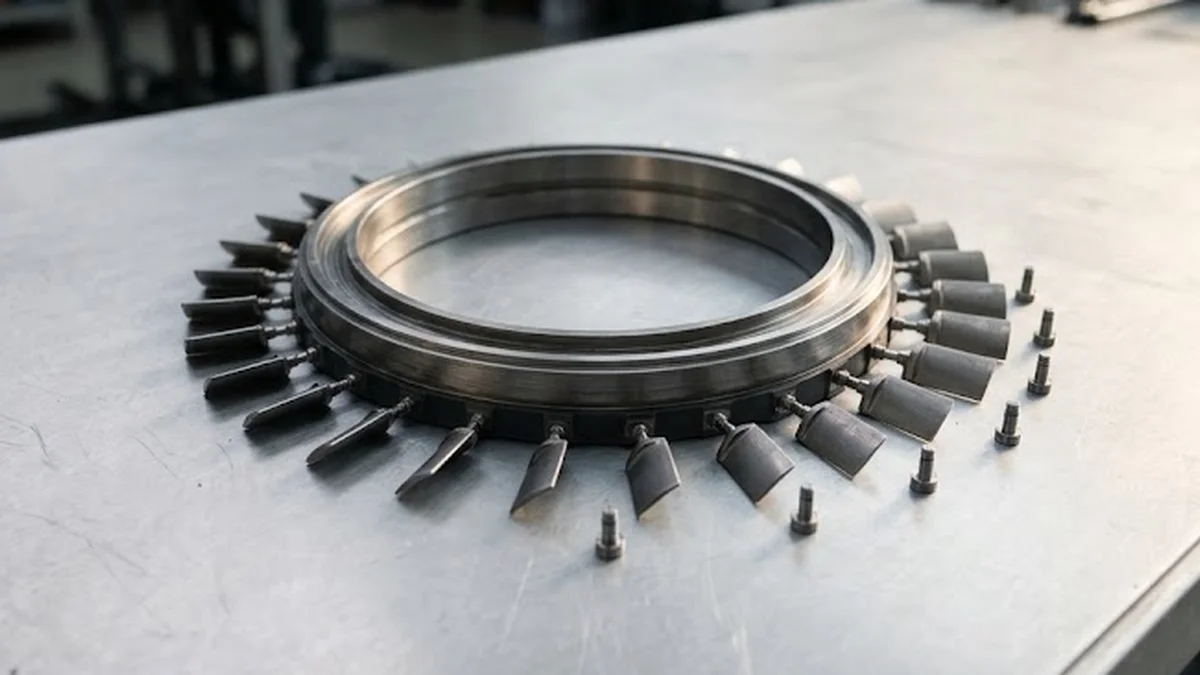
One of the most effective mechanical developments is variable turbine geometry (VTG or VNT), common in modern turbodiesel powertrains and select high-performance petrol vehicles. By incorporating a ring of movable aerodynamic guide vanes around the turbine wheel perimeter, the engine control unit (ECU) can actively alter the angle and nozzle area through which exhaust gases hit the turbine blades. At low engine speeds or sudden throttle application, the vanes pivot closed to create narrow nozzles, accelerating gas velocity and spooling the rotor instantly. Variable vane response takes under 100 milliseconds to adjust geometry across changing load commands. Once high exhaust volume is reached, the vanes open wide to prevent excessive backpressure.
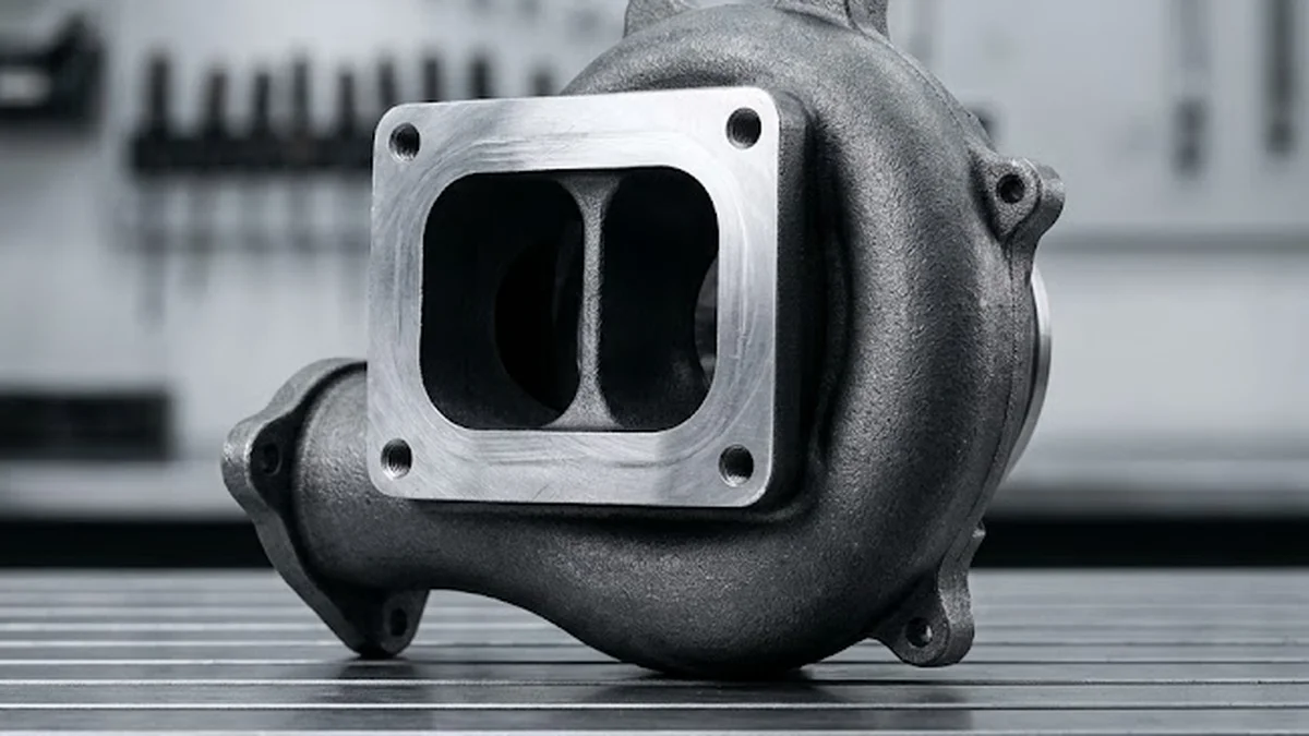
Another major technological milestone is the twin-scroll turbocharger design, which divides the turbine housing into two independent spiral channels paired with separated exhaust manifold runners. In a conventional four-cylinder engine, cylinder exhaust pulses interfere with one another due to valve overlap, diluting the kinetic energy entering the turbine. By grouping cylinders whose exhaust valves do not open simultaneously (such as cylinders 1 and 4 into one scroll, and cylinders 2 and 3 into the second scroll), exhaust pressure pulses strike the turbine wheel with uninterrupted frequency and force, cutting lag noticeably without requiring movable internal hardware.
Key takeaway: Modern turbo lag is fundamentally mitigated by aerodynamic and thermodynamic optimization—such as variable vane geometry and twin-scroll pulse management—which accelerate the turbine wheel without sacrificing high-rpm airflow capacity.
Additional innovations include ceramic ball-bearing center cartridges, which reduce shaft friction by up to 50 percent compared to conventional hydrodynamic bronze journal bearings, and lightweight titanium-aluminide (TiAl) turbine wheels that cut rotational inertia significantly. In hybrid powertrains, 48-volt electric auxiliary compressors (e-turbos) spin an electric compressor wheel instantly upon throttle tip-in, forcing positive pressure into the intake manifold before exhaust gas flow has even begun to build.
Diagnosing abnormal turbo lag: mechanical fault or normal behavior?
Every turbocharged internal combustion vehicle exhibits a baseline level of transient response delay designed into its factory calibration. However, when a vehicle develops sluggish acceleration, delayed boost onset, or a sensation that power delivery has become dramatically slower than normal, technicians and owners must determine whether they are observing normal turbo lag or an escalating mechanical fault. Identifying failing turbo symptoms early prevents secondary engine damage resulting from oil starvation or compressor wheel fragmentation.
A sudden increase in spool delay frequently stems from pressure leaks in the intake tract or exhaust tract. If a silicone boost hose cracks or the intercooler end-tank seal degrades, the compressor wheel must work significantly harder and longer to overcome the escaping air mass before reaching target manifold pressure. Similarly, cracked exhaust manifolds or leaking turbine inlet gaskets allow exhaust thermal energy to escape into the engine bay rather than driving the turbine blades.
Internal mechanical degradation within the turbocharger itself also degrades transient response. Excessive radial or axial play in the journal bearings causes the turbine and compressor wheels to drag against their respective housings, slowing acceleration. In variable geometry turbochargers, diesel soot and carbon accumulation frequently cause the internal nozzle vanes to bind. When the vanes stick in an open position, the turbocharger behaves like an oversized fixed-geometry unit, generating severe lag and poor low-end responsiveness.
When investigating abnormal spool delays in a workshop setting, follow this structured diagnostic checklist:
- Conduct a pressurized smoke test on intake and boost tract: Pressurize the intake plumbing from the compressor outlet to the throttle body at 1.0 bar to verify the integrity of all charge hoses, intercooler welds, and vacuum connections.
- Inspect the wastegate and variable vane actuator operation: Connect a manual vacuum or pressure hand-pump to the pneumatic actuator—or use diagnostic scan tool bi-directional controls on electronic actuators—to verify full, unhindered mechanical stroke without binding or hesitation.
- Perform a physical shaft and wheel inspection: Remove the intake inlet duct to access the compressor inducer. Check the wheel for foreign object damage, bent blade tips, oil contamination, and verify that the shaft rotates freely by hand without contacting the housing bore.
- Analyze live engine data and boost deviation: Log requested manifold absolute pressure (MAP) against actual MAP during a wide-open throttle run. A persistent deviation where actual boost lags several hundred millibars behind requested boost confirms a mechanical or pneumatic control deficit.
For modern downsized powertrains, maintaining factory-specified response characteristics requires exact component matching. For instance, replacement applications relying on a precision assembly like the Turbo MAHLE 030TC11001000 require strict adherence to original calibration standards to ensure the electronic actuator and internal vane mechanism interface properly with engine control software. Technicians can cross-examine vehicle engine codes and part numbers through our comprehensive turbocharger reference database to verify exact mechanical compatibility.
Standard exchange solutions and turbocharger maintenance
When diagnostic procedures reveal that a turbocharger has suffered internal mechanical wear, compromised bearings, or severe carbon binding of its variable geometry mechanism, continuing to operate the vehicle risks catastrophic failure. Debris from damaged turbine or compressor wheels can enter the engine combustion chambers or plug the exhaust aftertreatment system, resulting in expensive collateral damage.
Standard exchange (remanufacturing) represents the industry standard solution for restoring factory performance, reliability, and transient throttle response. Rather than purchasing an untested used unit from a salvage yard—which may possess worn bearings or stuck vanes—a remanufactured unit undergoes rigorous disassembly, ultrasonic cleaning, dimensional inspection, dynamic balancing of the rotating assembly on high-speed VSR equipment, and precise flow-bench calibration of the variable nozzle mechanism. This standard exchange process is operated through our standard exchange core deposit process, which recycles the valuable cast housings while replacing all wear components with brand-new precision parts.
Proper installation practices are essential to preserve the operational lifespan and transient response of any replacement turbocharger. The installation process must always be entrusted to a qualified professional mechanic acting as an independent third party. A certified technician will ensure that the engine oil supply and return lines are thoroughly flushed or replaced, the intercooler is completely cleared of residual oil deposits, and the newly installed unit is manually pre-lubricated with fresh engine oil prior to first engine startup. Dry starting a newly mounted turbocharger damages journal bearings within seconds, introducing immediate friction that permanently impairs rotor acceleration and causes premature failure.
In summary, while turbo lag remains an inherent physical characteristic of exhaust-driven forced induction systems, modern aerodynamic engineering and precision remanufacturing keep transient delays to an imperceptible minimum. Motorists and automotive workshops looking to restore original throttle response and engine efficiency can explore our complete remanufactured turbocharger catalog to identify compatible standard exchange units tailored to their specific vehicle make, engine displacement, and power rating.
A question?
Get in touch directly.

Discussion
Our advice related to Turbocharger
 Turbocharger
What Is a Twin Scroll Turbo? How It Works & Benefits
Discover what is a twin scroll turbo, how divided exhaust scrolls eliminate lag, boost low-end torque, and optimize efficiency. Complete technical guide.
 Turbocharger
Why Is My Turbo Whistling? Warning Signs and Causes
Is your turbo whistling under acceleration? Discover the differences between normal spooling and mechanical failure, from boost leaks to bearing play.
 Turbocharger
How Much HP Does a Turbo Add? Power Gains & Costs
Learn how much horsepower a turbo adds across engine sizes, what drives replacement costs, and how standard exchange delivers full factory performance.