
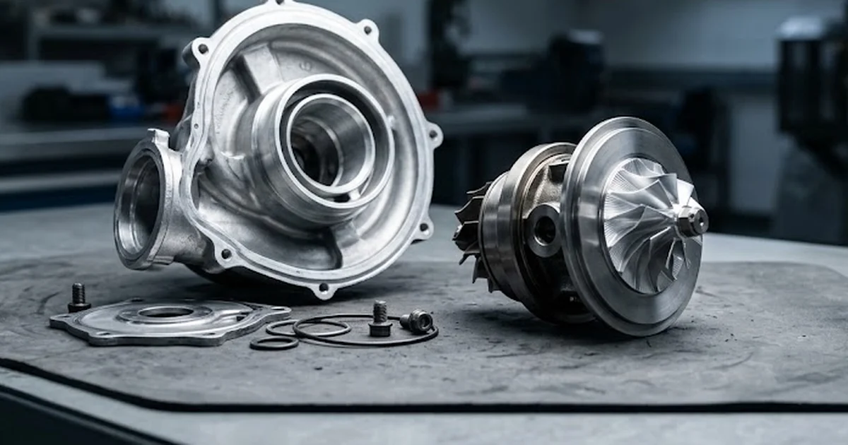
Turbocharger testing: how to diagnose the fault before you order
Master systematic turbocharger testing to pinpoint power loss, smoke, and whistling before ordering a replacement standard exchange turbocharger.
Understanding Turbocharger Testing: Why Systematic Diagnosis Precedes Replacement
Performing structured turbocharger testing before ordering a replacement component is the single most effective way to avoid unnecessary expenses and repeat mechanical failures. When a vehicle displays sudden power loss, persistent exhaust smoke, or limp mode activation, condemning the forced induction unit outright is an understandable reflex. However, remanufacturing engineering records consistently demonstrate that a significant proportion of returned core units suffered from external engine malfunctions rather than primary manufacturing defects. In a standard exchange system, where damaged assemblies are returned under a core deposit arrangement, installing a fresh unit onto a compromised engine leads directly to immediate secondary failure.
Modern turbochargers are precision fluid-dynamic machines operating at rotational speeds exceeding 200,000 revolutions per minute and exhaust gas temperatures surpassing 800 degrees Celsius. Because the turbocharger operates at the convergence point between the lubrication, air induction, and exhaust systems, it registers failure symptoms when any of these supporting systems deteriorate. A restricted oil feed line, a split boost hose, a saturated diesel particulate filter, or a faulty mass air flow sensor will cause symptoms identical to internal bearing collapse. Diagnosing the underlying root cause is mandatory before deciding whether mechanical replacement is genuinely required.
Engineering standards reinforce this methodical approach. As documented in the standardised turbocharger test procedures of SAE J 1826, the test procedures outlined in this SAE Standard are applicable to turbocharging systems having either fixed- or variable-geometry. Both configurations require comprehensive evaluation of their peripheral circuits before removing mechanical assemblies.
A replacement turbocharger must never be fitted to an engine before establishing why the previous unit failed; resolving oil feed restrictions, boost leaks, and exhaust blockages is the only way to prevent immediate repeat breakdown.
Physical Shaft Play and Housing Inspection: Step-by-Step Mechanical Verification
Before unbolting the turbocharger assembly from the exhaust manifold, a direct mechanical assessment of the central rotating assembly—commonly referred to as the cartridge or CHRA (Center Housing Rotating Assembly)—can be carried out directly in the engine bay. Accessing the compressor wheel requires uncoupling the fresh air intake ducting and crankcase ventilation breather pipes. With the inlet port exposed, both visual and tactile inspections provide definitive data on internal bearing health.
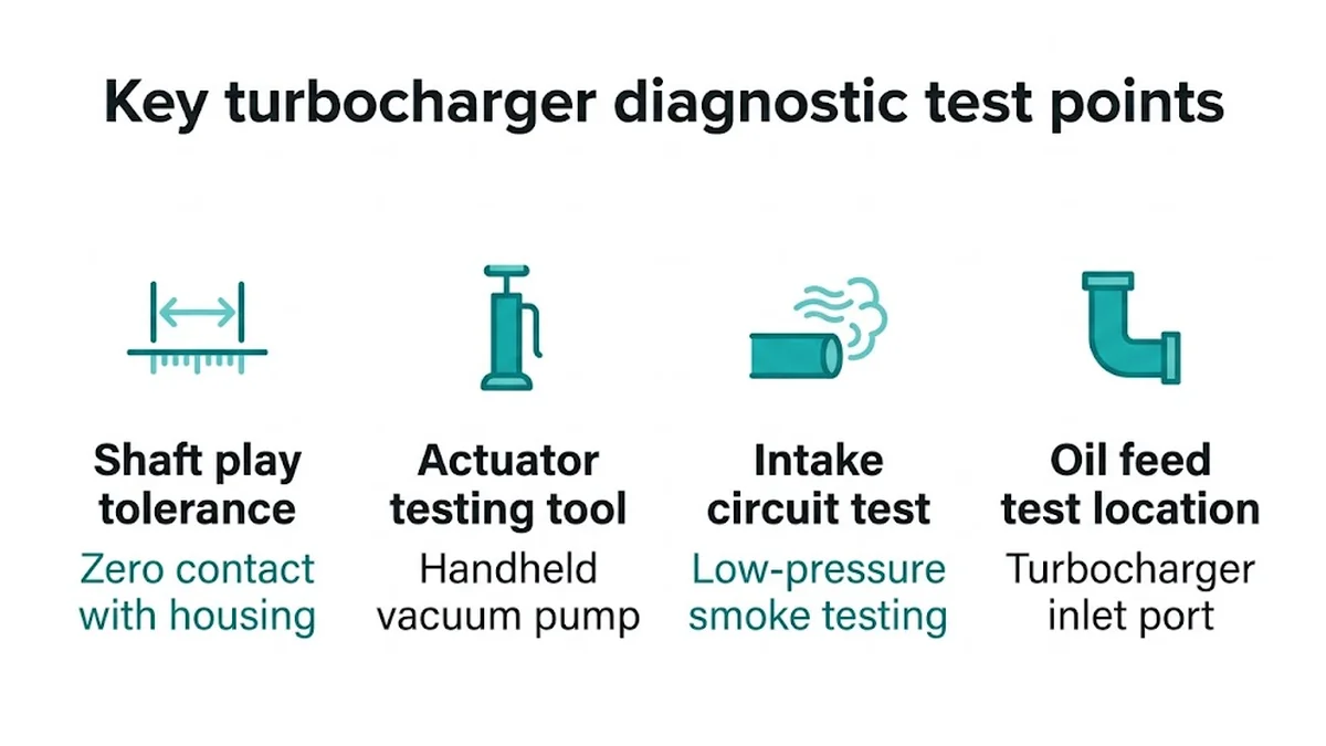
Automotive turbochargers rely on hydrodynamic floating journal bearings. When the engine is stationary and oil pressure is zero, a slight degree of lateral clearance is engineered into the assembly to accommodate the pressurised oil film during normal operation. This normal micro-clearance must never be confused with terminal mechanical wear. During mechanical verification, the following threshold must be respected: Shaft play tolerance: Zero contact with housing under radial finger pressure.
To execute a thorough physical shaft inspection, proceed through the following diagnostic sequence:
- Ensure the engine is completely cold and switched off to avoid burns and contact with moving components.
- Detach the flexible intake ducting connected to the compressor housing inlet to gain clear, unobstructed visibility of the compressor wheel nut and cast blades.
- Gently grasp the central compressor wheel retaining nut using your thumb and index finger, applying moderate radial (side-to-side and up-and-down) pressure while slowly rotating the shaft.
- Verify that the wheel turns smoothly without binding, grinding, or gritty resistance, ensuring that the blade tips never contact the internal contour of the aluminium compressor housing.
- Apply axial force by gently pushing and pulling the central shaft along its rotational axis; there should be virtually zero perceptible back-and-forth movement. Perceptible axial end-play confirms that the internal brass or bronze thrust bearing collar has completely broken down.
- Inspect the leading edges of the compressor vanes under bright light for foreign object damage, such as rounded blade tips, notch fractures, or erosion caused by particulate ingress through a substandard air filter.
If the compressor blades show signs of contact with the alloy housing or the shaft displays distinct axial float, internal structural failure is verified. Cross-referencing these physical findings with documented failed turbo symptoms enables motorists and technicians to determine whether bearing failure was initiated by oil breakdown or foreign debris impact.
Actuator and Variable Geometry Mechanism Testing: Pneumatic vs Electronic Controls
A turbocharger that fails to generate expected boost pressure or frequently triggers overboost fault codes is not necessarily suffering from core mechanical breakdown. In modern diesel and petrol applications, boost pressure is continuously modulated either by a traditional wastegate valve or by variable nozzle turbine (VNT/VGT) guide vanes. When the regulating actuator or its internal linkages seize, the turbocharger cannot adjust its aerodynamic profile, causing the engine control unit (ECU) to default into emergency limp mode.
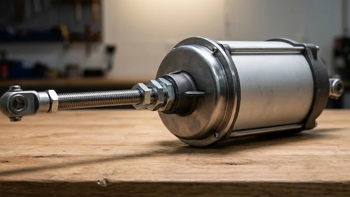
Diagnostic testing methods diverge depending on whether the unit employs a pneumatic vacuum actuator or an electronic rotary actuator (REA/SREA). For pneumatic checks, the essential bench instrument is: Actuator testing tool: Handheld vacuum pump equipped with a clear pressure gauge. Connecting the pump directly to the actuator nipple allows you to apply vacuum progressively. The internal diaphragm should hold vacuum indefinitely without bleeding down, and the operating rod must stroke smoothly across its full travel range—typically between 10 and 15 millimetres—without sticking, stuttering, or mechanical notchiness.
Electronic actuators require bidirectional diagnostic scan tools or manual linkage decoupling. Disconnecting the linkage circlip allows the technician to manually sweep the variable geometry mechanism lever by hand to determine whether stiffness originates within the turbine housing or inside the actuator gearbox. The table below outlines the diagnostic profiles of major regulation mechanisms:
| Turbocharger Regulation Technology | Characteristic Failure Symptom | Primary Diagnostic Test Method | Key Physical Observation |
|---|---|---|---|
| Pneumatic Wastegate (Fixed Geometry) | Underboost at high engine load or whistling under acceleration | Pressure application via hand pump directly to actuator chamber | Stuck wastegate valve seat, split internal rubber diaphragm, or loose linkage pin |
| Pneumatic Variable Nozzle (VNT / VGT) | Limp mode during uphill acceleration and overboost fault codes | Vacuum hold test and manual movement of the control lever | Carbon binding inside the unison ring, sticking guide vanes, or torn vacuum capsule |
| Electronic Rotary Actuator (SREA / REA) | Instantaneous limp mode upon engine startup and intermittent boost loss | Bidirectional scan tool actuation test and manual rod travel check | Stripped internal plastic reduction gears, broken motor worm drive, or cracked solder joints |
If manual testing reveals that the external linkage sweeps freely across its designed range while the pneumatic diaphragm fails to hold vacuum, replacing the individual actuator capsule may resolve the fault. Conversely, if carbon deposits have locked the variable geometry unison ring inside the turbine housing, the complete turbocharger assembly requires replacement or professional overhaul.
Air Intake, Boost Leak, and Exhaust Circuit Diagnostic Procedures
A substantial percentage of suspected turbocharger failures are ultimately traced to breaches in the pressurized charge air circuit. A split rubber intercooler hose, a punctured charge air cooler, or a dislodged joint clip allows pressurized air to escape into the atmosphere. The engine control unit detects a mismatch between metered air intake and manifold boost pressure, triggering an underboost fault and placing the vehicle in limp mode. Simultaneously, escaping high-pressure air produces a sharp whistling or rushing hiss under acceleration.
Distinguishing between an aerodynamic air leak and mechanical bearing failure is vital. Reviewing our technical guide on whistling turbo symptoms clarifies how acoustic anomalies often originate outside the turbocharger casing. To locate elusive charge pipe fractures, the recommended method is: Intake circuit test: Low-pressure smoke testing applied through the induction ducting. Introducing dense diagnostic smoke at approximately 0.5 bar into the sealed intake system immediately exposes hair-line fractures in plastic pipes, split intercooler end tanks, or weeping joint seals without requiring complete engine strip-down.
On the exhaust side, excessive backpressure represents a silent killer of turbocharger assemblies. A saturated diesel particulate filter (DPF) or melted catalytic converter obstructs the free evacuation of hot exhaust gases. The resulting thermal and pressure buildup pushes exhaust gas and soot backward past the turbine dynamic piston ring seal, entering the bearing housing and carbonising the engine oil. Diagnostic evaluation of the exhaust circuit must include:
- Reading DPF differential pressure sensor live data at idle and at 2,500 RPM to identify exhaust restrictions before installing new hardware.
- Inspecting the exhaust manifold and turbine flange surfaces for telltale black soot trails that indicate cracked castings or blowing gaskets.
- Checking crankcase pressure by examining the positive crankcase ventilation (PCV) valve; a blocked breather pressurises the engine sump, preventing oil from draining freely from the turbocharger and forcing oil past the seals into the intercooler.
- Verifying the condition of the catalytic converter core for internal crumbling or structural detachment that could obstruct the exhaust downpipe.
Oil Supply, Lubrication Pressure, and Contamination Analysis
Hydrodynamic turbocharger bearings rely entirely on an uninterrupted cushion of pressurised engine oil to prevent metal-to-metal contact with the central steel shaft. Deprived of oil for even four seconds under load, bearing temperatures skyrocket, leading to instant metal transfer, shaft discolouration, and complete structural seizure. Therefore, evaluating lubrication integrity is the most critical stage of turbocharger testing.
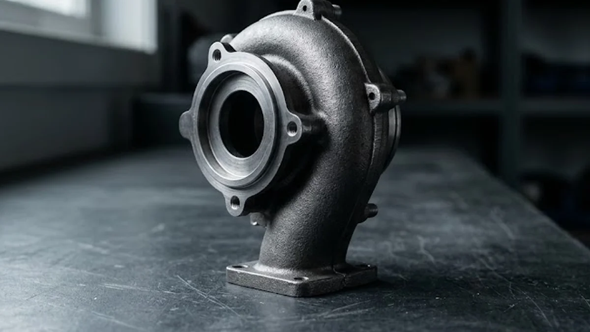
When verifying lubrication delivery prior to restart, verify the following: Oil feed test location: Turbocharger inlet port under engine cranking conditions. To conduct this flow test safely, disable fuel injection or engine ignition, disconnect the rigid oil feed line at the turbocharger bearing housing, place the open line end into a clean collection vessel, and crank the engine for ten seconds. A steady, substantial stream of clean engine oil must emerge. A weak dribble or delayed delivery indicates a blocked feed pipe, a sludged oil pickup strainer, or a worn oil pump.
Technicians must also inspect the extracted oil for physical contamination:
- Fine metallic sparkle or copper-coloured sediment indicating severe bottom-end engine wear from crankshaft bearings.
- Thick black sludge or carbon particulates caused by extended oil drain intervals and thermal breakdown around the exhaust housing.
- Fuel dilution, detectable by an intense diesel odour and low viscosity, frequently caused by uncompleted DPF regenerations washing unburnt fuel past piston rings into the sump.
- Coolant contamination presenting as a pale emulsified residue, pointing toward head gasket or oil cooler failure.
Whenever a compromised turbocharger is replaced, installing an approved new gasket kit alongside a brand-new oil feed pipe is mandatory trade practice. Rigid feed pipes running adjacent to hot exhaust manifolds frequently suffer from internal carbon coking that cannot be flushed clean. Furthermore, professional installation by an independent automotive workshop or qualified mechanic guarantees that critical pre-lubrication procedures—such as manually filling the bearing cartridge cavity with clean oil before initial startup—are strictly observed.
Identifying Part References and Selecting the Correct Replacement Assembly
When methodical diagnostic testing confirms that the rotating core, turbine wheel, or variable geometry assembly has suffered irreparable mechanical wear, selecting the exact replacement unit is the next crucial step. Motorists often attempt to locate parts using general vehicle descriptions such as engine displacement and year of manufacture. However, manufacturers frequently fit multiple distinct turbocharger variants across the lifespan of a single engine family to satisfy evolving emissions standards and power outputs.
Precise part identification relies on the metal data plate riveted or laser-etched onto the aluminium compressor housing. This plate contains two indispensable numbers: the turbocharger manufacturer part number (assigned by manufacturers like Garrett, BorgWarner, IHI, Mitsubishi, or Mahle) and the vehicle manufacturer part number. Consulting official OEM references ensures absolute interchangeability regarding oil pipe angles, exhaust downpipe bolt spacing, and electronic actuator pin configurations.
Matching the replacement unit to exact vehicle engine codes (such as 1.5 dCi K9K, 1.6 HDi DV6, or 2.0 TDI EA288 variants) eliminates the risk of ordering an incompatible component. For example, specific engine configurations require dedicated factory-calibrated assemblies like the Turbo MAHLE 030TC11001000 reference, engineered to meet precise boost maps and mounting specifications. Reviewing detailed requirements for professional turbo repair and installation ensures that all necessary ancillary items, including sump flushing and intake cleaning, are addressed concurrently.
In summary, systematic turbocharger testing prevents misdiagnosis, protects your investment, and ensures that a replacement unit delivers long-lasting reliability. Rather than guessing, verifying mechanical shaft tolerances, actuator response, boost hose integrity, and oil feed pressure establishes a definitive diagnosis. If testing confirms that your unit has reached the end of its service life, browse our comprehensive standard exchange turbocharger catalog to locate the precision-engineered component engineered for your specific vehicle motorisation.
Frequently asked questions
Everything you need to know about this topic.
A question?
Get in touch directly.

Discussion
Our advice related to Turbocharger
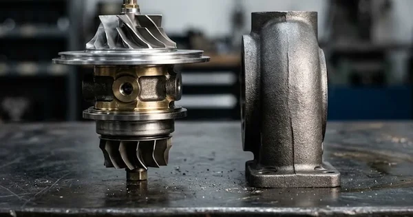 Turbocharger
What Is Turbo Lag? Causes, Symptoms & Solutions | autoKUR
Understand what turbo lag is, how it differs from boost threshold, and how to diagnose sluggish throttle response. Expert mechanical advice by autoKUR.
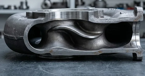 Turbocharger
What Is a Twin Scroll Turbo? How It Works & Benefits
Discover what is a twin scroll turbo, how divided exhaust scrolls eliminate lag, boost low-end torque, and optimize efficiency. Complete technical guide.
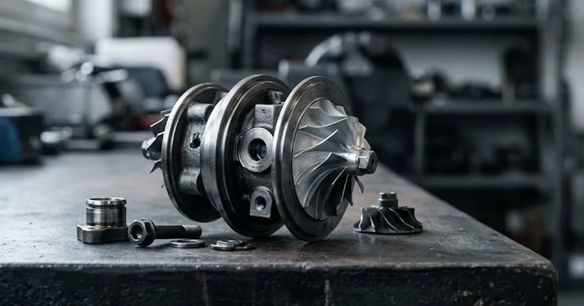 Turbocharger
Why Is My Turbo Whistling? Warning Signs and Causes
Is your turbo whistling under acceleration? Discover the differences between normal spooling and mechanical failure, from boost leaks to bearing play.