
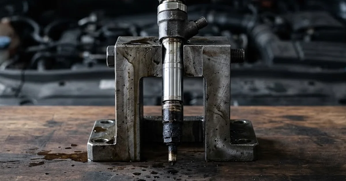
How to remove a stuck injector
Learn how to remove a stuck injector safely without damaging the cylinder head. Discover proven chemical, mechanical, and hydraulic extraction techniques.
Understanding Why a Fuel Injector Seizes in the Cylinder Head
Modern common-rail diesel engines operate under extreme thermal and mechanical loads, with peak cylinder pressures and multiple injection events per cycle. In this punishing operating environment, removing a fuel injector should theoretically be a straightforward mechanical procedure: loosen the high-pressure fuel pipe, unbolt the injector retaining clamp, and withdraw the assembly axially from its bore. In practice, workshop technicians and experienced motorists frequently encounter injectors that appear welded to the aluminium cylinder head, resisting all conventional hand efforts.
Several chemical and mechanical mechanisms contribute to this severe binding within the injector well:
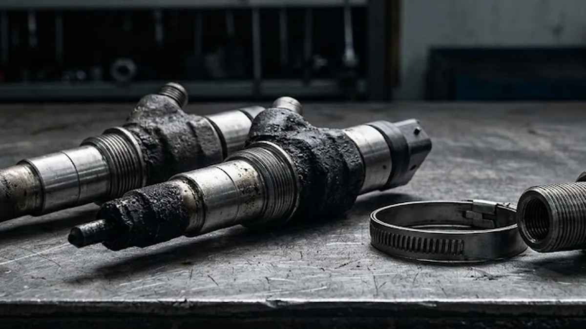
- Combustion gas blow-by: When the lower copper sealing washer fatigues, erodes, or was improperly torqued during a previous intervention, incandescent combustion gases bypass the seal and escape upward along the narrow clearance between the injector body and the cylinder head bore. As these exhaust gases cool, they deposit sticky unburnt hydrocarbons, heavy soot, and tar-like residues. Over thousands of miles, this mixture petrifies into a dense, crystalline carbon compound colloquially known in workshops as black death.
- Galvanic corrosion bonding: Common-rail injectors feature high-tensile alloy steel bodies, whereas modern cylinder heads are cast from aluminium alloys. In the presence of ambient moisture, condensation, or road salt spray entering past loose scuttle panels and engine covers, these two dissimilar metals form an electrochemical galvanic cell. The aluminium oxidises, producing white aluminium oxide powder that expands in volume, filling the micro-tolerances of the bore and locking the steel injector casing into place.
- Thermal deformation and carbon packing: Repeated heat cycles between ambient temperature and 90°C cause differential thermal expansion between the aluminium head and the steel injector body. Microscopic carbon particles become tightly wedged into the resulting expansion gaps, creating a mechanical friction lock that defies standard pullers.
- External water contamination: Blocked rain drainage channels at the base of the windscreen allow rainwater to drip steadily onto the top of the engine, pooling directly around the recessed injector wells. This standing water accelerates rust along the injector clamping forks and seizing rings.
Addressing a seized injector requires a methodical plan that respects the structural integrity of both the injector casing and the cast aluminium cylinder head. Rushing the procedure with brute force frequently results in broken injector studs, cracked valve covers, or ovalised injector wells that require costly machine-shop remediation.
Assessing the Seizure: Carbon Caking Versus Galvanic Bonding
Before selecting an extraction tool or applying mechanical force, an accurate assessment of the failure mode is essential. Carbon-caked injectors exhibit different resistance characteristics compared to galvanically oxidised components, and each scenario demands a tailored intervention strategy. A visual inspection of the cylinder head area provides immediate diagnostic clues: thick, shiny black crusting piled around the retaining clamp points to combustion gas leakage, whereas powdery grey or white deposits accompanied by surface rust on the clamping fork indicate galvanic oxidation driven by water ingress.
Never apply lateral leverage against the cylinder head or pry under the electrical connector. Vertical alignment is critical during extraction to avoid fracturing the injector body or ovalising the injector well.
Acoustic and tactile feedback also reveal the severity of the seizure. If a dedicated open-ended crows-foot spanner applied to the designated injector body flats produces a fractional rotational movement without excessive torque, the carbon bond is beginning to yield. Conversely, if the injector body flexes elastically without any rotational slip, the unit is seized along the entire length of its cylindrical shaft by metal oxide growth. In severe galvanic cases, applying rotational torque will shear the injector casing before the bond releases.
Essential Chemical and Thermal Preparation Before Extraction
Direct mechanical pulling should never be attempted on a cold, dry seized injector. High-grade penetrating solvents and controlled heat cycling represent the safest preliminary steps to soften carbon deposits and exploit differing thermal expansion coefficients between the aluminium cylinder head and the steel injector casing.
To prepare the assembly for chemical soaking and thermal release, follow this sequence:
- Decontaminate the injector recess: Blow away loose dirt, road grit, and flaky rust using compressed air while wearing protective eyewear. Scrape away the superficial carbon crust surrounding the injector collar using a brass pick to expose the junction between the injector body and the bore.
- Depressurise and isolate the fuel circuit: Ensure the ignition is completely switched off and disconnect the battery ground terminal. Disconnect the electrical injector plug and unthread the common-rail high-pressure pipe, immediately fitting clean protective blanking caps over the rail outlet and the injector inlet to prevent microscopic contamination.
- Apply targeted carbon-softening chemicals: Flood the injector well with a dedicated industrial carbon dissolving foam or high-wicking synthetic penetrating oil formulated to dissolve baked hydrocarbons. Allow the chemistry sufficient dwell time to penetrate downward along the injector shaft.
- Cycle engine operating temperature: If the engine is still runnable on its remaining cylinders, warm the block to normal operating temperature. The aluminium cylinder head expands at roughly twice the rate of the steel injector casing, momentarily widening the clearance within the bore and drawing the penetrating fluid deeper into the seizure zone.
- Apply high-frequency vibration: Using an air chisel fitted with a blunt brass drift or a dedicated pneumatic vibration hammer at low air pressure, deliver micro-impacts to the injector clamp bolt area or the upper body flats. These rapid micro-shocks crack the brittle crystalline structure of the carbon matrix without distorting the internal valves.
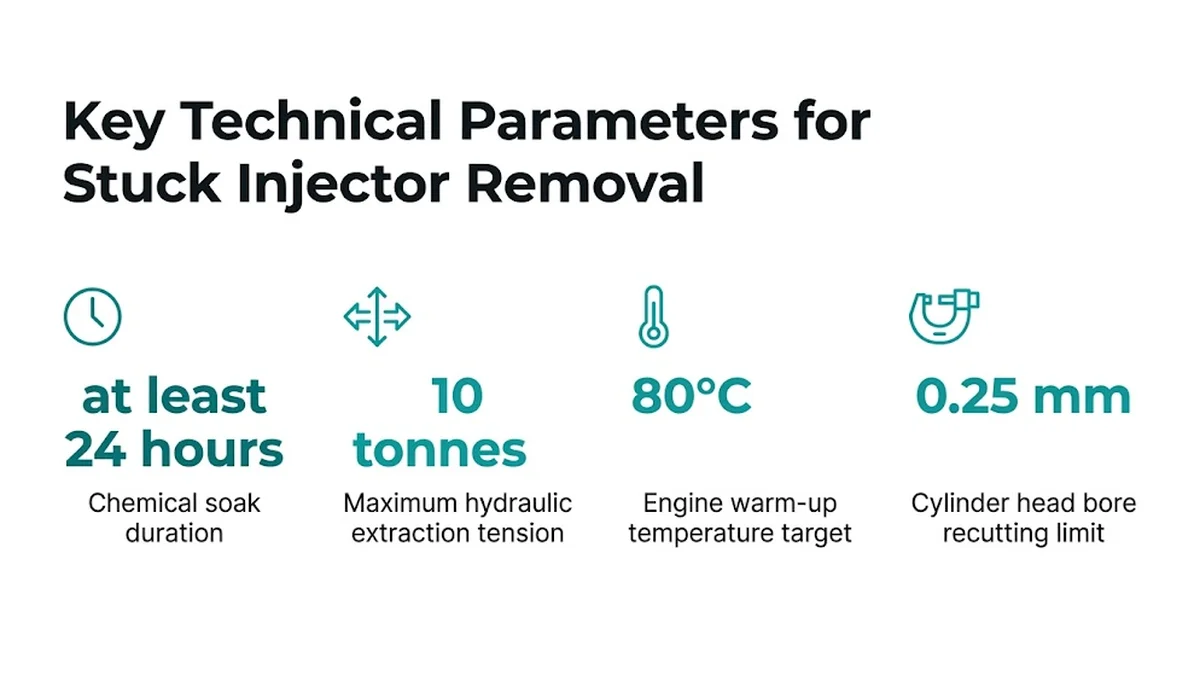
Key workshop extraction parameters to observe:
- Chemical soak duration: at least 24 hours
- Maximum hydraulic extraction tension: 10 tonnes
- Engine warm-up temperature target: 80°C
- Cylinder head bore recutting limit: 0.25 mm
When penetrating oil sits around the injector base for the full recommended duration, it continuously softens the tar-like binders holding the carbon granules together, reducing the eventual extraction tension required by more than half.
Mechanical and Hydraulic Extraction Techniques for Stuck Injectors
When chemical soaking and heat cycling fail to release the injector by hand, mechanical pulling equipment becomes necessary. The choice of pulling device depends on the physical clearance inside the engine compartment and the estimated resistance of the seizure.
Specialist extraction tooling generally falls into three distinct categories:
- Impact slide hammer extractors: A slide hammer attaches to the injector either via an internal adaptor threaded into the top of the body (after removing the electrical solenoid or piezo head) or through an external fork gripping the injector collar. Sliding a heavy steel weight upward against a mechanical stop generates repetitive axial shock loads. While effective for moderate carbon seizures, aggressive slide hammering can stretch the internal components of the injector or deform its casing, rendering the old unit unsuitable for standard remanufacturing processes.
- Mechanical support bridge pullers: A rigid steel bridge spans across the cylinder head, resting squarely on solid structural points such as valve cover bolt bosses or cylinder head casting ribs. A high-tensile threaded pulling spindle engages the injector body threads and pulls smoothly upward as a heavy-duty thrust bearing nut is tightened. Mechanical bridges deliver smooth, progressive linear tension without sudden impact shocks, drastically reducing the risk of shock-fracturing the cylinder head casting.
- Hollow-piston hydraulic ram extractors: For stubborn commercial vehicle and passenger car diesel engines where mechanical pullers risk snapping high-tensile threaded rods, a hollow hydraulic cylinder is mounted over the support bridge. Powered by a manual or pneumatic hydraulic pump, the ram generates massive axial pulling force smoothly up to the component safety limit. This continuous, shock-free upward pressure draws the most severely locked injectors out of the head while keeping pulling forces strictly perpendicular to the bore axis.
- Pneumatic resonance extractors: These modern tools combine continuous vertical pulling tension with high-frequency acoustic air pulses. The resonant vibration continuously shatters the molecular adhesion between carbon soot and the metal surfaces while steady tension extracts the unit millimeter by millimeter.
Regardless of the tool selected, maintaining pure axial alignment is vital. If a pulling spindle tilts even two degrees off-centre, lateral side-loading will gall the soft aluminium bore wall and permanently damage the cylinder head casting.
Comparison of Injector Extraction Methods and Risk Factors
Selecting the appropriate extraction methodology requires balancing tool availability against the physical condition of the engine and the potential risk to surrounding components. The following comparative overview details the practical applications and mechanical risks associated with each primary technique.
| Extraction Method | Recommended Seizure Scenario | Primary Tooling Required | Component Risk | Extraction Success Probability |
|---|---|---|---|---|
| Chemical Soak & Manual Rotation | Early-stage carbon blow-by with visible wet soot | Carbon-dissolving fluid, crows-foot spanner, brass picks | Minimal risk to head; slight risk of rounding body flats | Moderate on fresh leaks; low on hardened carbon |
| Impact Slide Hammer | Moderate carbon crusting with accessible overhead clearance | Slide hammer (3 kg to 5 kg), threaded top adaptor | High risk of stretching injector casing; risk of shock damage to head | Good on light commercial diesels; inconsistent on deep wells |
| Supporting Bridge Mechanical Puller | Severe carbon crusting and early galvanic oxidation | Rigid steel bridge, high-tensile spindle, ball-thrust nut | Low risk if bridge feet are correctly supported; spindle wear | High on passenger car common-rail engines |
| Hydraulic Hollow Ram Extractor | Extreme seizure, heavy galvanic bonding, deep cylinder wells | Hollow hydraulic ram, 10-tonne pump, hardened tie rods | Moderate risk of cylinder head deflection if unsupported; core destruction | Very high on commercial vans and high-mileage engines |
| Pneumatic Resonance Extractor | Hardened carbon matrix resisting static tension | Air resonance gun, pressure regulator, axial adaptors | Very low risk to cylinder head; preserves core geometry | High across all common-rail diesel platforms |
Understanding these trade-offs allows technicians and dedicated DIY mechanics to escalate extraction force progressively rather than applying destructive impact loads at the earliest sign of resistance. For detailed baseline instructions on standard unseized removal steps, consult our comprehensive How to Remove a Fuel Injector: Step-by-Step Guide before moving on to heavy-duty extraction rigs.
Cleaning the Cylinder Head Bore and Installing the Replacement Unit
Successfully freeing a stuck injector represents only half of the repair. Leaving pulverized carbon or corrosion debris inside the injector bore guarantees that the replacement unit will fail prematurely or blow past its copper seat within a few hundred miles.
Complete the post-extraction reconditioning using this meticulous procedure:
- Seal the combustion chamber port: Insert a dedicated rubber or brass sealing plug into the narrow nozzle passage at the very bottom of the injector well. This prevents loose carbon chips, metallic dust, and solvent run-off from falling directly onto the piston crown or scoring the cylinder bore.
- Clean the bore walls: Mount a cylindrical brass wire brush into a low-speed drill or hand driver. Run the brush up and down the bore walls while vacuuming simultaneously with a narrow workshop suction nozzle. Avoid abrasive steel brushes that scratch the soft aluminium bore surface.
- Ream the lower sealing seat: Carbon build-up and escaping combustion flame frequently pit and erode the flat circular seat at the base of the cylinder head. Using a precision injector seat cutter with the correct pilot guide matching the engine bore diameter, gently rotate the tool clockwise by hand with light downward pressure. Remove only the bare minimum of material required to produce a clean, uniform, shiny metallic face, strictly respecting the specified limit of 0.25 mm.
- Extract the sealing plug and vacuum: Carefully retrieve the nozzle passage plug and use a compressed air blowgun paired with high-volume suction to verify that not a single speck of carbon remains in the chamber or on the seat.
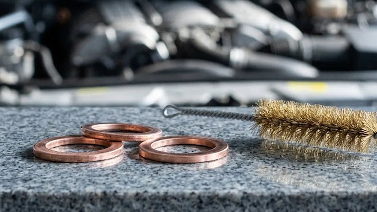
- Fit a new sealing washer from a gasket kit: Never reuse an old copper washer, and never stack two washers together. Fit a fresh, vehicle-specific copper crush washer supplied in a certified gasket kit, verifying that its thickness matches OEM technical data for that exact engine code.
- Apply high-temperature ceramic grease: Lightly coat the cylindrical steel body of the replacement injector with metal-free, white ceramic mounting grease rated up to 1400°C. This protective barrier prevents moisture ingress and eliminates future galvanic bonding between the steel body and the aluminium cylinder head. Keep the nozzle tip and spray holes completely dry and free from grease.
- Torque clamping hardware to specification: Lower the injector cleanly into the bore without dropping it onto the copper washer. Install a brand-new stretch clamp bolt, as injector clamp bolts are torque-to-yield fasteners designed for single use. Torque the fastener to the initial stage using a calibrated torque wrench, followed by the specified angle rotation.
When high pulling forces have been applied to dislodge a seized injector, the internal piezoelectric actuators, solenoid coils, or micro-machined valve needles are almost always compromised. Reinstalling an extracted unit that suffered heavy slide hammer shocks or high hydraulic pulling tension risks erratic fuel delivery, excessive return flow, and piston crown melting. Instead, replacing the extracted component with a fully remanufactured unit—such as a certified Injector Bosch 0414720028 calibrated to original factory parameters—restores accurate multi-point injection timing and emission compliance.
When purchasing remanufactured common-rail units, returning the old extracted core under the standard core deposit system ensures that recyclable metallurgical components are returned to specialized remanufacturing centres, provided the external casing has not been crushed or sheared during removal.
Recognising Critical Limits: When to Stop and Seek Specialist Intervention
Every mechanical intervention has a boundary beyond which continued unguided force results in catastrophic failure. When extracting stuck injectors, applying excessive tension without specialised knowledge can snap the injector body in half, leaving the lower nozzle assembly and pressure spring wedged deep inside the cylinder head below the rocker cover.
Stop extraction immediately and seek professional workshop support if any of the following warning conditions emerge:
- Injector body elongation: If the upper casing visibly stretches or the extractor adaptor threads begin stripping out of the injector body, the steel has reached its ultimate tensile yield point. Continued pulling will shear the injector into two pieces.
- Cylinder head casting deflection: If the support legs of a mechanical bridge puller begin sinking into or distorting the aluminium surface of the cylinder head or valve cover bosses, release tension immediately to avoid punching a hole into the oil gallery or water jacket.
- Total mechanical lockup above maximum hydraulic ratings: When a 10-tonne hydraulic ram reaches its designated working pressure without achieving any axial upward displacement of the injector, the unit is galvanically bonded across its entire surface area. Continued pressurisation risks explosive tool failure.
- Snapped injector nozzle in the well: If an injector shears off flush with the cylinder head, stop drilling attempts with hand tools. Attempting to drill out hardened steel injector nozzles by hand invariably leads to the drill bit wandering off-centre into the much softer aluminium cylinder head casting, destroying the head beyond repair.
Specialist mobile extraction technicians possess spark-erosion EDM (Electrical Discharge Machining) equipment and precision alignment rigs capable of disintegrating the seized steel sleeve directly inside the cylinder head without requiring engine removal or cylinder head replacement. Recognizing when to pause protects the engine block from irreversible destruction.
Synthesis and Sourcing Quality Reconditioned Fuel Injectors
Removing a stuck diesel injector demands patience, systematic chemical preparation, and dedicated pulling equipment designed to apply pure axial force. By resisting the temptation to use lateral pry bars, allowing synthetic penetrating agents sufficient time to break down baked soot, and utilising rigid support bridges or hydraulic hollow rams, technicians can overcome severe carbon crusting and galvanic bonding while safeguarding the structural integrity of the cylinder head.
Once the seized unit is successfully extracted, the bore must be cleaned, reamed, and reassembled with a fresh copper seal and high-temperature ceramic anti-seize paste to guarantee long-term reliability. If an extraction attempt has distorted the internal components or compromised the nozzle body, explore our dedicated fuel injector category to select a reliable standard exchange unit matched to your exact vehicle engine code and power specification.
Frequently asked questions
Everything you need to know about this topic.
A question?
Get in touch directly.

Discussion
Our advice related to Injector
 Injector
Reconditioned Injectors: New vs Exchange vs Used
Compare new, reconditioned, and used fuel injectors. Discover technical differences, core deposit savings, and calibration standards for reliable engine repair.
 Injector
Car Injector Replacement: Fitting & Refitting Guide
Discover what car injector replacement really involves: mechanical seating, copper washer renewal, clamp torquing, ECU coding, and high-pressure fuel priming.
 Injector
Does Petrol Injector Cleaner Work? Truth & Limits
Does petrol injector cleaner work? Discover what fuel additives can clean, where they fail on direct injection engines, and when replacement is necessary.