
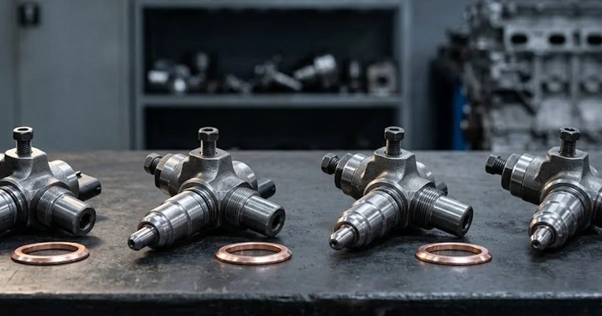
Car injector replacement: what fitting or refitting the part really involves
Discover what car injector replacement really involves: mechanical seating, copper washer renewal, clamp torquing, ECU coding, and high-pressure fuel priming.
Understanding car injector replacement: technical scope and operating principles
Undertaking a car injector replacement represents one of the most critical interventions on a modern internal combustion engine. Far from a basic mechanical disassembly, installing or refitting a fuel injector directly impacts the thermodynamic efficiency, acoustic balance, and exhaust emissions of the powertrain. Modern common rail diesel and direct-injection petrol engines operate under extreme thermal and mechanical stresses, requiring absolute precision during both physical mounting and electronic integration.
The fuel injector serves as the terminal actuator of the injection system, atomising fuel directly into the combustion bowl at pressures that frequently exceed several hundred to over a thousand atmospheres. When an injector suffers from internal hydraulic bypass, electrical actuator degradation, or tip nozzle coking, the engine control unit loses its ability to meter microsecond-level fuel quantities. Replacing the component restores combustion stability, but achieving original equipment performance requires understanding how the injector interfaces with the cylinder head, the high-pressure fuel rail, and the engine management system.
Every injector replacement encompasses four interconnected engineering facets that must be managed concurrently:
- Hydraulic sealing under extreme pressure: Ensuring that all fuel feed unions withstand peak rail pressure without microscopic weeping, which poses severe fire and pressure-drop hazards.
- Combustion chamber isolation: Guaranteeing that expanding combustion gases cannot escape past the injector nozzle shank, which depends entirely on proper seat preparation and washer deformation.
- Thermal dissipation pathway: Facilitating heat transfer from the injector nozzle tip through the copper crush washer and into the water-cooled cylinder head casting.
- Electronic calibration matching: Aligning the physical flow profile of the replacement unit with the electronic injection maps stored within the vehicle control module.
Critical pre-installation checks: diagnosis, contamination, and core inspection
Before fitting a replacement unit, establishing the root cause of the previous component failure is mandatory. Fuel injectors rarely fail prematurely without external factors. Fitting a replacement unit into a contaminated or compromised fuel circuit invariably triggers repeat failure within a few hundred miles of operation. Technicians and knowledgeable motorists must thoroughly inspect the condition of the fuel filter, check for water contamination, and examine the fuel return lines for abnormal backpressure.
A crucial verification involves inspecting the high-pressure circuit for microscopic metallic debris. When an internal component inside the high-pressure pump suffers mechanical scuffing or roller failure, it sheds metallic swarf throughout the fuel rail and injector feed lines. If fine metal filings are detected in the fuel filter bowl or pump metering valve, fitting new injectors without thoroughly flushing the tank, replacing lines, and changing the pump will destroy the replacement nozzles almost instantly. Furthermore, when disassembling seized or carbon-welded components from the cylinder head, following a specialized stuck injector safe extraction guide prevents shearing the injector body or cracking the aluminium casting.
Under the standard exchange remanufacturing model, managing the used core is an integral part of the process. The core deposit system ensures that original manufacturer cores are returned in a rebuildable state, allowing specialised workshops to clean, measure, calibrate, and rebuild injectors to rigorous standards. Inspecting the old unit upon removal also provides valuable forensic data: external carbon buildup points to washer failure, whilst blue discolouration on the nozzle tip indicates severe overheating from lean combustion or insufficient cooling.
The technical parameters and mounting requirements vary significantly across different automotive injection architectures:
| Injection Technology | Typical Rail Pressure | Seating & Sealing Method | Calibration & Coding Requirement |
|---|---|---|---|
| Common Rail Solenoid | 1400 to 2000 bar | Single-use copper crush washer, clamp bolt | 6 to 9-character IMA alphanumeric code |
| Common Rail Piezoelectric | 1800 to 2500 bar | Precision-matched copper seal, stretch bolt | Multi-point ISA or IMA voltage offset coding |
| Unit Injector (Pumpe-Düse) | Up to 2050 bar | Viton O-ring pack, copper seal, rocker lash | Mechanical rocker clearance, BIP calibration |
| Direct Injection Petrol (GDI) | 150 to 350 bar | Deformable Teflon combustion seal ring | Flow class sorting number or QR matrix code |
Step-by-step mechanical fitting procedure: clean seats and precise torquing
The mechanical installation of a fuel injector requires surgical cleanliness and meticulous adherence to torque specifications. Even a microscopic particle of carbon or grit trapped between the injector nozzle shoulder and the cylinder head seat will prevent the copper washer from sealing flat. This leads to high-pressure combustion blow-by, commonly referred to as chuffing, which rapidly encases the injector in black hard carbon slag and overheats the electrical solenoid.
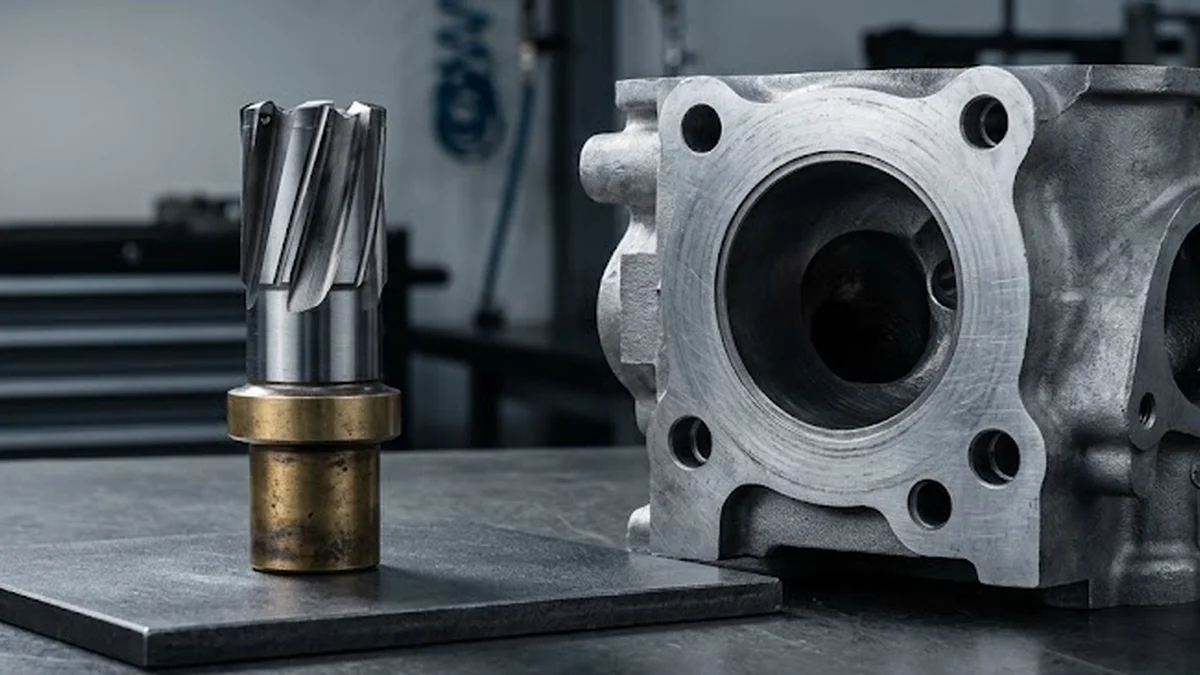
Seat preparation must be executed with dedicated cleaning brushes and specialized brass seat cutters. Technicians must gently reface the bottom of the injector bore, removing glazed carbon without cutting excessively into the parent aluminium of the cylinder head. For specialised configurations such as the Injector Bosch 0414720028 unit injector, the installation also demands replacing the side viton O-rings, renewing the eccentric rocker adjusters, and setting the bottom-dead-centre plunger pre-load with a dial test indicator. Disassembly steps should be reviewed using a step-by-step fuel injector removal guide to ensure all protective caps and brackets are properly handled.
To ensure a flawless mechanical fit, the physical installation must follow an uncompromising sequence:
- Bore decontamination and vacuuming: Clean the injector well using solvent-resistant nylon brushes and vacuum all loose carbon particles from the combustion chamber through the glow plug or injector orifice.
- Seat inspection and refacing: Guide a pilot-guided seat cutter into the bore by hand to lightly scrape away burnt carbon until a uniform, bright metallic ring is visible across the entire seating perimeter.
- Washer fitment and ceramic greasing: Fit a brand-new copper crush washer of the exact manufacturer-specified thickness onto the nozzle tip, and apply a thin film of high-temperature ceramic mounting grease exclusively to the injector body shaft, keeping the nozzle tip completely dry.
- Injector alignment and clamp tightening: Lower the injector straight into the bore without twisting, position the retaining clamp evenly, and torque the retaining stretch bolt using the initial torque setting followed by the mandatory angular rotation specified by the engine manufacturer.
- High-pressure line connection: Align the high-pressure steel delivery pipe by hand to ensure the conical flare seats square against the injector inlet fitting, then tighten the union nut with an open-ended crowfoot torque wrench to prevent applying torsional strain to the injector body.
ECU calibration and coding: programming IMA codes for cylinder balance
Modern diesel common rail injectors operate with tolerances measured in fractions of a micrometre. Because microscopic variations in nozzle hole drilling, internal spring tension, and magnetic coil response exist even among brand-new components, no two injectors exhibit identical delivery characteristics across the entire rev range. To compensate for these physical variations, manufacturers test each finished injector on an automated test bench across diverse operating regimes, including pilot injection, pre-injection, main injection, and full load.
The resulting flow correction matrix is encoded into an alphanumeric string known as an IMA (Injector Quantity Adjustment) code, typically between 6 and 9 digits for solenoid systems, or a multi-character matrix for piezoelectric units. During refitting, this individual code must be written into the engine control unit using a professional diagnostic tool, associating each specific alphanumeric string with its corresponding cylinder number. The engine control unit uses this data to advance or retard electrical pulse timings by mere microseconds, ensuring exact fuel delivery per stroke.
Key takeaway: Every fuel injector replacement requires renewing the copper crush washer, recutting or thoroughly cleaning the injector seat, and entering the unique calibration code into the engine control unit to prevent combustion blow-by and cylinder imbalance.
Neglecting injector coding causes the engine control unit to calculate fuelling based on generic baseline profiles or the calibration data of the discarded unit. This discrepancy creates cylinder power imbalance, audible diesel knock, rough idling, elevated tailpipe smoke, and premature clogging of the diesel particulate filter due to incomplete combustion soot loading.
Post-installation bleeding, priming, and initial startup protocols
Once mechanical installation and electronic calibration are complete, commissioning the fuel system requires strict priming protocols. Modern high-pressure common rail pumps and precision injector valves rely entirely on diesel fuel for hydrodynamic lubrication. Cranking an engine with air trapped in the high-pressure lines creates dry friction within the pump rollers and causes needle scuffing inside the injector nozzles, generating permanent damage before the engine even fires.
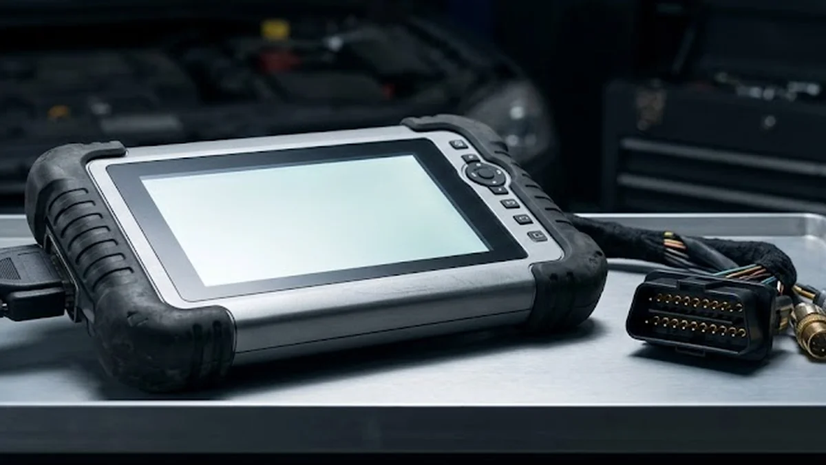
Priming must be carried out using the vehicle diagnostic software to activate the electric fuel lift pump for several sequential cycles, or by connecting an external vacuum bleeding tool to the fuel return circuit. Cranking the starter motor continuously to force fuel through is strictly prohibited. Technicians must purge the low-pressure circuit until a continuous, bubble-free stream of fuel circulates through the filter housing and high-pressure pump inlet.
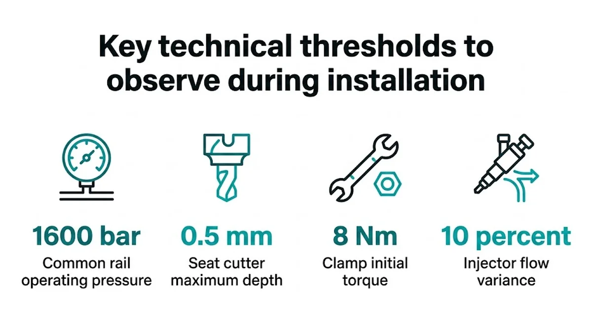
Key technical thresholds to observe during installation:
- Common rail operating pressure: 1600 bar
- Seat cutter maximum depth: 0.5 mm
- Clamp initial torque: 8 Nm
- Injector flow variance: 10 percent
During the initial engine startup, maintain idle without revving the engine while monitoring live diagnostic data parameters. Technicians should verify that the common rail fuel pressure matches the target setpoint instantaneously, and observe individual cylinder smooth running control values. A healthy installation demonstrates injector correction values within tight tolerances, confirming balanced cylinder contribution and leak-free hydraulic performance.
Synthesis: ensuring long-term reliability for your replacement fuel injectors
Car injector replacement is an exacting discipline combining hydraulic hygiene, precise mechanical assembly, and digital engine calibration. Treating the procedure as a simple component swap risks repeat failures, combustion leakage, or severe cylinder head damage. By identifying underlying contamination, refacing the injector seat, utilizing new single-use hardware, and entering the unique IMA calibration codes, motorists and mechanics safeguard engine longevity and restore optimal fuel economy.
Because common rail systems generate extreme pressures capable of penetrating human skin and require dedicated calibration equipment, having the replacement carried out by a qualified automotive repair professional is strongly recommended. A professional workshop possesses the seat-cutting fixtures, high-precision torque angle gauges, and diagnostic software required to execute every step in strict accordance with engineering tolerances.
- Always diagnose the initial failure cause and verify the absence of metal swarf before installing new components.
- Never reuse copper crush washers, clamp stretch bolts, or deformed high-pressure pipe flare fittings.
- Ensure the cylinder head seat is flat, clean, and free of carbon before introducing the new washer.
- Program individual IMA calibration codes into the engine control unit prior to attempting the first engine start.
- Thoroughly prime and bleed the fuel system to protect the high-pressure pump and injector needles from dry friction.
Whether addressing a persistent cylinder misfire, resolving excessive exhaust smoke, or completing scheduled powertrain maintenance, selecting precision-tested components from our fuel injector catalogue ensures your vehicle benefits from verified flow rates, strict remanufacturing tolerances, and long-lasting mechanical reliability.
Frequently asked questions
Everything you need to know about this topic.
A question?
Get in touch directly.

Discussion
Our advice related to Injector
 Injector
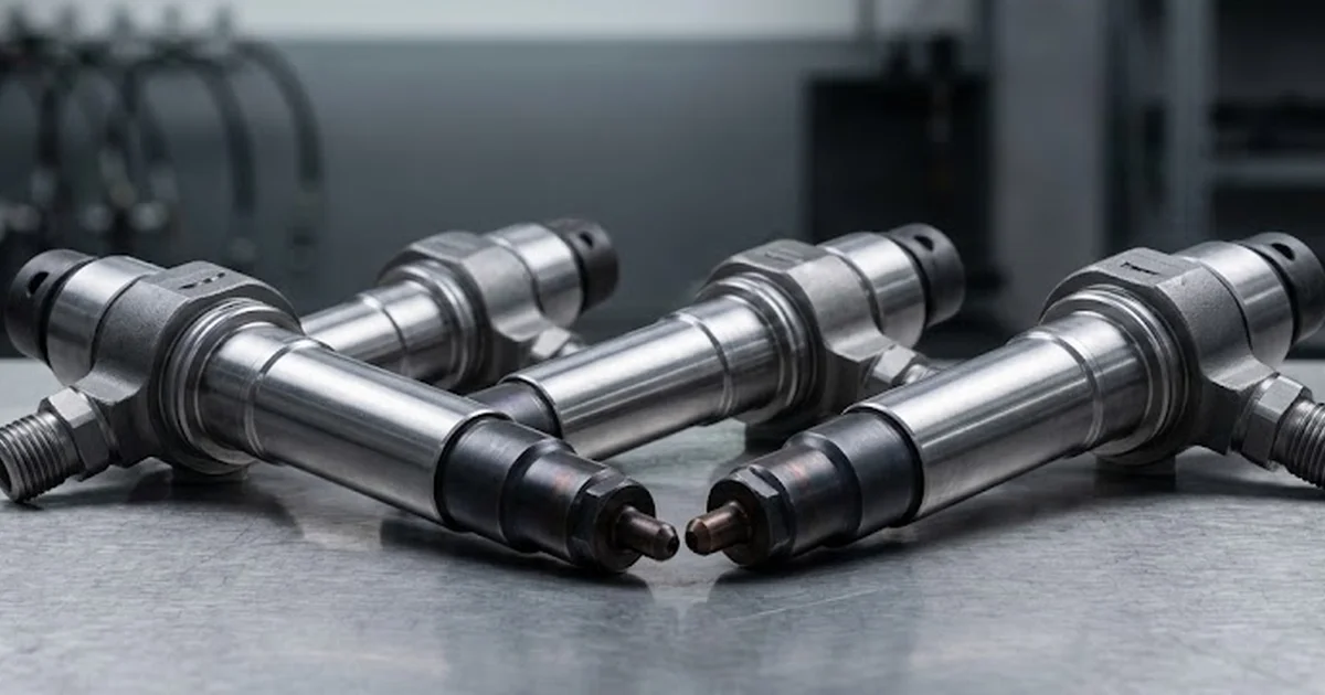
Reconditioned Injectors: New vs Exchange vs Used
Compare new, reconditioned, and used fuel injectors. Discover technical differences, core deposit savings, and calibration standards for reliable engine repair.
 Injector
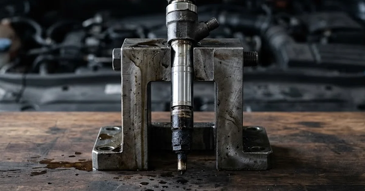
How to Remove a Stuck Injector: Safe Extraction Guide
Learn how to remove a stuck injector safely without damaging the cylinder head. Discover proven chemical, mechanical, and hydraulic extraction techniques.
 Injector
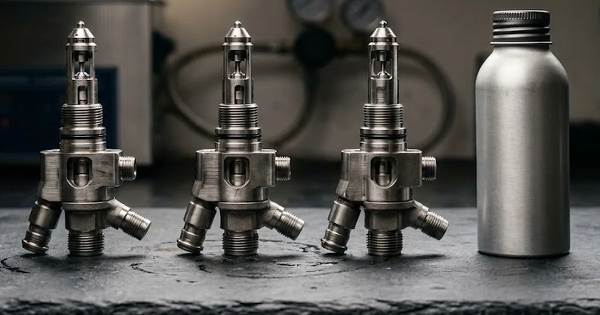
Does Petrol Injector Cleaner Work? Truth & Limits
Does petrol injector cleaner work? Discover what fuel additives can clean, where they fail on direct injection engines, and when replacement is necessary.